This document is relevant only for the following hardware:
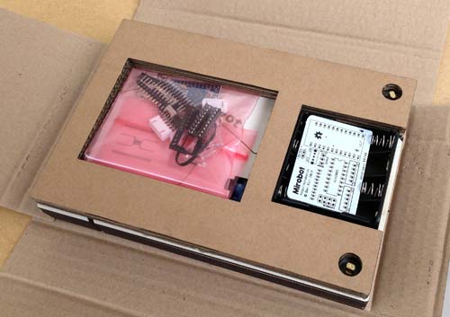
When you unwrap the package you should see a pink bag with the components in it, a white PCB and the black battery box. Take these out and put the rest of the package to one side for now.
To assemble the PCB you will need:
It is highly recommended to watch this soldering tutorial before starting if you’re not used to soldering. Soldering isn’t too difficult, but it’s worth taking the time to make sure it’s done well so it is more likely to work first time.
WARNING: Soldering involves temperatures hot enough to melt metal, so please be careful and use appropriate safety wear
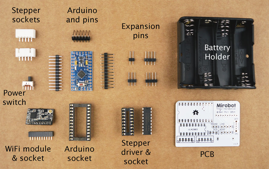
Here are all of the parts that you will need to use for this stage. There are some other parts in the pink bag that will be used at a later stage so put these away for now.
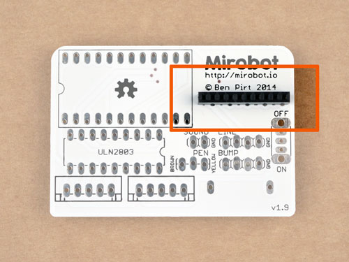
Solder the WiFi socket in place. Be careful not to use too much solder on this part because it can ‘wick’ up into the socket and make it hard to get the module in.
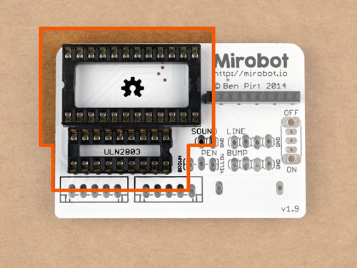
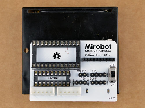
Solder both of the chip sockets in to place. Take care to put the notches on the short end in line with the outline on the PCB. The larger one should have the notch on the left and the smaller should have the notch on the right. Sometimes the pins on these get slightly bent so make sure they are all straight before putting them in.
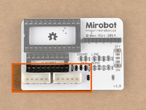
Solder the stepper sockets in place. You need to make sure that the side with two notches in it is at the edge of the board - check the photo. They should clip satisfyingly into place.
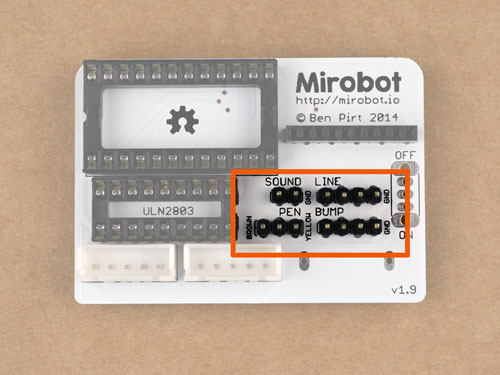
Solder the expansion pins in to place. These should be inserted with the small end of the pins going through the PCB from the top down.
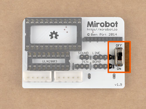
Solder in the power switch. This can go either way around.
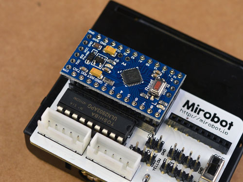
Now we need to solder the pins on to the Arduino board we are using. The best way of doing this is to push both rows of pins into the Arduino socket as shown in this photo. Now is also a good time to put the stepper driver chip into its socket. You need to make sure the small notch on one end of the chip aligns with the notch on the socket. Check the photo if you’re unsure.
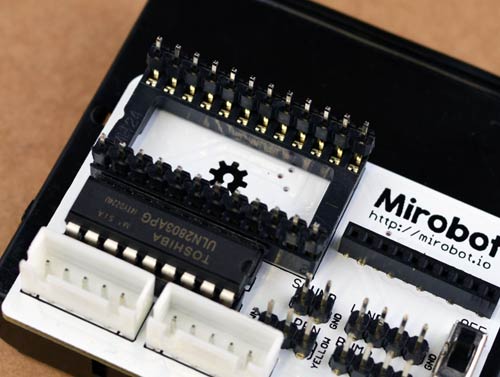
You can then put the Arduino onto these pins and solder them in. Doing it this way makes sure they are well aligned and will fit in and out nice and easily. The pins are quite small but take your time and it shouldn’t be too tricky.
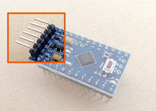
If you need to reprogram the Arduino at some point in the future, you can take it out of the socket and solder on the programming pins as shown in the photo. You don’t need these on in order to use Mirobot though.
First, inspect your soldering. There should be no messy bits of solder bridging from the pins to other parts of the PCB. If there are, use the soldering iron to remove them. We’re going to test the board before soldering the battery pack on because once it’s in place it would need removing if there are any errors:
If the LEDs don’t turn on then turn it off straight away because there’s most likely a short circuit. Take a careful look at the back of your board to double check for any bits of solder that might be bridging between pins. Don’t solder the battery pack on until you have successfully done this step! It’s worth making sure at this point that you’re using fully charged batteries because low batteries can cause issues that may make this step fail.
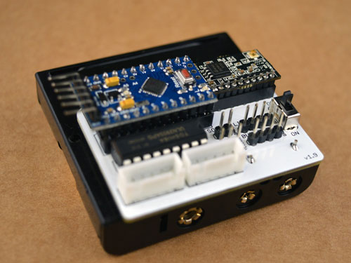
It’s time to attach the battery holder. First, peel off the cover over the sticky pad on the battery holder. Then push the pins on the holder through the PCB from behind like in this picture. Once you’ve pushed it on so it sticks then you should carefuly solder it. Put the batteries in the holder and turn the switch on again to make sure the LEDs still come on and flash correctly. If the LED starts flashing then the board is OK and you should start building the chassis


