This document is relevant only for the following hardware:
You should already have soldered together the PCB. Now it’s time to put the chassis together. The chassis is made out of the six panels shown below.
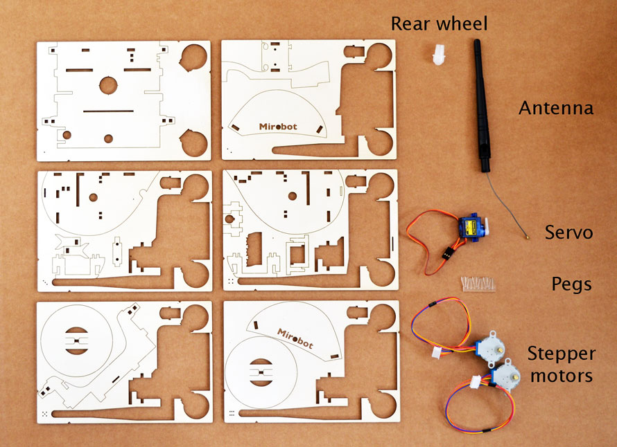
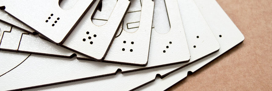
To help you figure out which piece is which look for the dots (like a dice) on each panel that help identify them which we’ll refer to in these instructions.
You’ll also need these parts that were left in the pink bag from the PCB build:
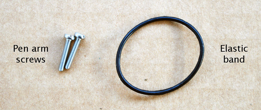
The elastic bands that are used to hold the panels together can come in handy as spares.
The only tool you will need for this assembly is a medium sized flat headed screwdriver.
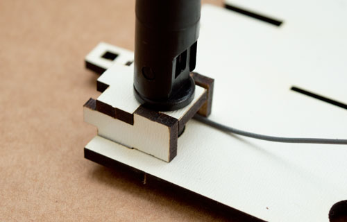
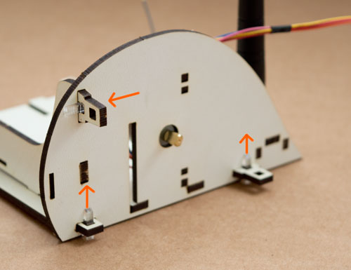
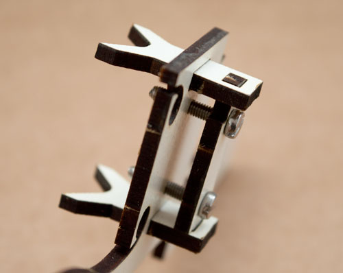
Be careful with this step because the antenna mount is quite fragile
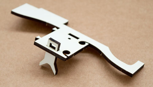
Find the antenna and the top antenna mount piece.
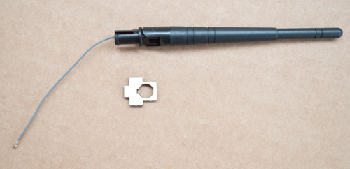
Put the antenna cable through the hole first, then gently push the base of the antenna through the hole, twisting as you push it through.
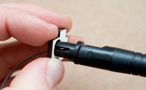
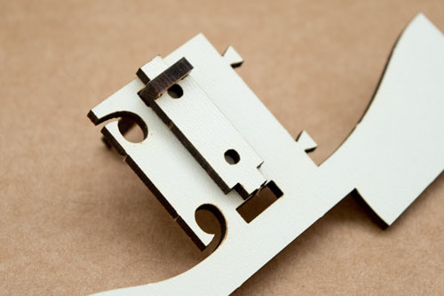
Once it is through the bracket, make sure it is rotated so the notch on the antenna aligns with the bracket.
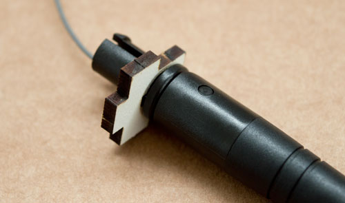
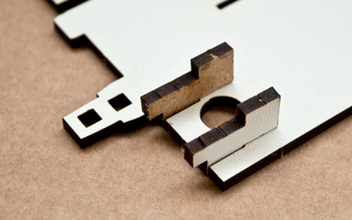
Put the two side pieces of the antenna mount into the base, making sure they are aligned as in the photo.
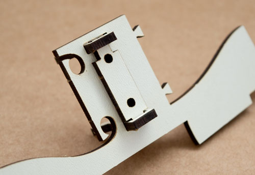
Pull the cable out through the slot in the antenna (see photo) because we don’t want it to go through the base, we want it to come out above the base
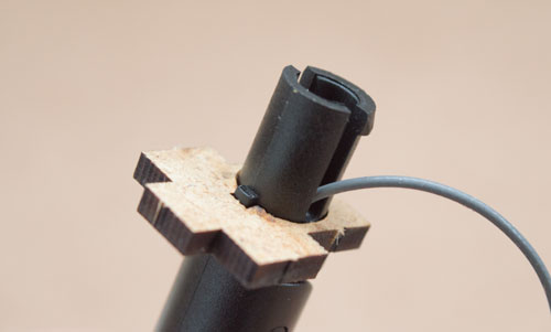
Making sure the base is flat on the table, push the antenna into the hole and then pick it up and push it all the way through.
Make sure that the top bracket fits into the side brackets.
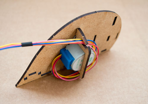
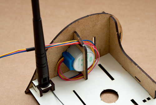
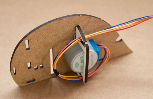
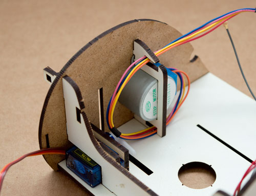
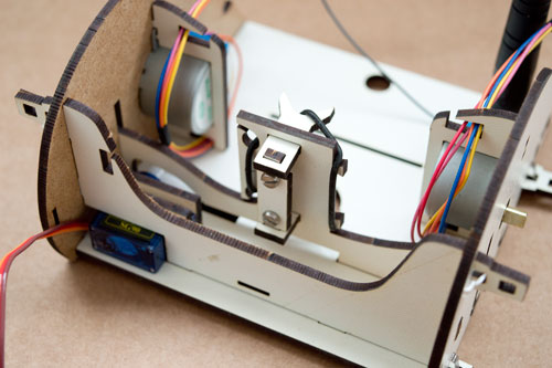
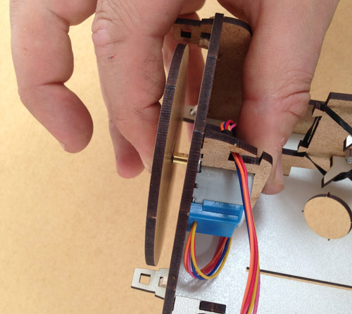
Find the left stepper motor bracket (on panel 4) and put the motor into it as shown in the picture. Make sure that the bracket goes through the two screw holes on the motor. Wind the cable once around it which will help keep the cable tidy but also helps to stop it falling out while you’re building it. The cable should go through the bottom hole first, then loop around the motor and go through the top hole. Once you have done this, slot it into the left side piece (on panel 4) making sure that the blue part of the motor with the cables coming out of it points to the back of the robot like in this picture.
Put the bulkhead (on panel 5) on to the chassis base (on panel 1) as shown.
Gently slide the side of the robot on to the chassis base, taking care to align it with all of the pieces sticking through it. This can sometimes get snagged - don’t force it on. If it’s not going on easily, make sure that all of the pieces are properly aligned with the holes.
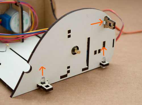
Snap off three of the small pegs and push them through the small holes against the side of the robot making sure that the flat side of the peg goes against the flat side of the robot. They should push through so that you can see the peg on either side of the hole. It is best to push the two bottom pegs in from the bottom up, otherwise they can push out when you pick up the robot. It can be helpful to use something hard to push them in to make sure they hold properly.
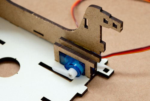
Slide the blue servo under the bulkhead on to the chassis base with its cable to the edge and then slot the two U shaped servo mounts (on panel 4) over the servo on either side of the plastic plates. They should slot into the holes on the base.
Place a stepper motor in the right side bracket (on panel 3) and put it into the right side piece (on panel 3) as shown. Wind the cable around in the same way as the first motor.
Slide the right side on to the base as you did on the other side, again taking care to make sure all of the parts are properly aligned. Do not force it on. If it is not sliding on easily, it just means something is not aligned.
Snap off three more pegs and peg it on the same as you did for the other side.
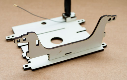
Put the main part of the robot to one side now and find the pieces for the pen arm (on panels 2, 3 and 4).
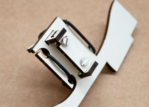
Push the top pen mount through the pen arm as shown in the photo, making sure that it is facing the right way.
Push the long end of the adjustment plate (that has two holes in it) up through the hole in the pen mount as shown in the photo.
Push the second pen mount through the pen arm pointing in the same direction as the first and slide the adjustment plate down into the second pen mount that you just put in.
Place the two screws through the holes in the bracket and screw them both in by the same amount.
These screws are used to adjust the pen so it is aligned with the centre of the wheels. If it’s not properly aligned you’ll get bumps at the corners of your lines when you draw.
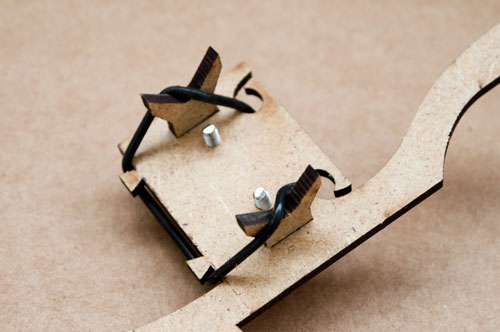
Hook the elastic band through the holes ond around the small pegs on the other side. You can hook the elastic on to the pen mounts to keep it tight until you put a pen in place. Felt tips pens work the best!
Slide one end of the pen arm into the slots in the main chassis, with the pen mounts facing inwards towards the hole in the base. Drop the other end down into place so that it sits in nicely.
Clip both wheels (on panels 5 and 6) on to the metal part of the stepper motor, making sure to align them correctly. It should be a reasonably tight fit. It is best to squeeze together with your thumb on the back of the motor and your finger on the wheel as shown in this picture.
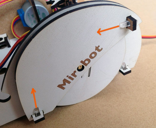
Slide the wheel covers (left wheel cover on panel 2 and right on panel 6) on to the tabs so that they cover the wheels then peg them on. There are two pieces like this and they will only go on one way with the logo facing the outside.
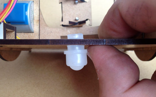
Push the white plastic caster wheel through the hole in the back. Don’t push directly on to the ball as this can damage it, push using the ridge around it.
Turn the switch on the PCB to Off and insert batteries. Fit the PCB into the slot. It should go in upside down with the white stepper sockets at the bottom like in this picture.
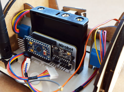
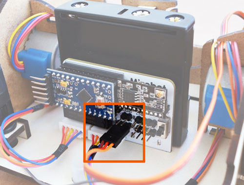
Connect both stepper motors. The plugs should only be able to go in one way.
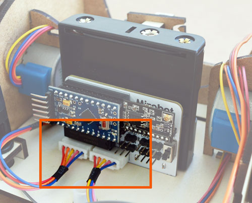
Connect the servo with the yellow cable at the right as marked on the PCB. Tuck the cable into the slots to keep it tidy as it passes along the chassis.
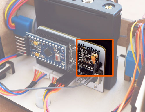
Remove the WiFi module, click the small connector on the end of the antenna cable on to the small circular socket on the WiFi module and then put it back in to its socket.
Well done! You’re ready to set up Mirobot, get the pen in place and start drawing. Don’t forget to turn it on!


