This document is relevant only for the following hardware:
First you’ll need to solder the line following addon together, then you’ll be able to start Mirobot following lines.
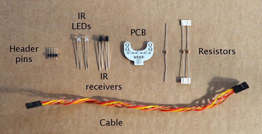
You’ll need to find the parts below to build the line following addon:
The tools you’ll need are:
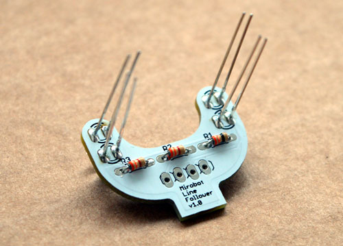
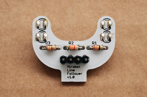
Solder in the two resistors that are the same into positions R2 and R3. They should have stripes matching those in the picture; orange, orange, red, gold.
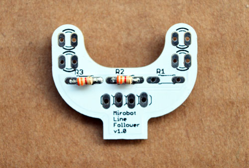
Solder in the remaining resistor into position R1. It should have stripes matching those in the picture; orange, orange, black, gold.
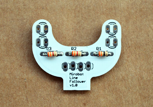
Clip off all of the long resistor legs once you’ve soldered all of the resistors in.
The line follower uses infrared to detect the line, but because infrared light is invisible, it’s difficult to know if you’ve got this part right or not so you’ll need to take extra care over this step.
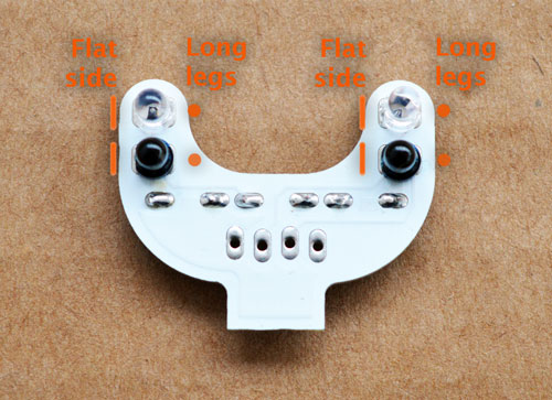
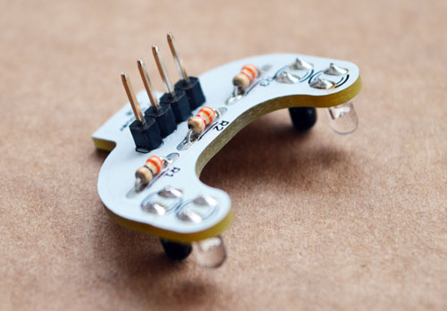
The clear LED and the black receivers need soldering in. Look carefully at them and you will see that one side of their body is flat and that they have one long leg (on the opposite side). We will use these to make sure we get them in the right way round.
We’ll also be soldering them on the opposite side to the resistors so the first thing to do is turn it over so you are looking at the side with no black lettering on it.
Now you should put the clear LEDs on the end of the arms and the black receivers next to them, like in the photo. The flat side should be on the left and the long leg should be in the right hand hole.
Check again that they are all facing the right way, solder them in and clip off the legs.
If you heat these LEDs too much they can break, so be careful to only use enough heat to melt the solder and not more
Solder the pin header in place on the top of the board. The short part of the pins should go through the hole and the long part should stick up (see the next photo if you’re unsure)
Now you’ve finished soldering, the line follower addon should look like this:
Slide the line follower addon in to the slot at the front of Mirobot and push on the cable so the yellow wire is on the left (with the robot facing forward). Take a look at this photo if you are unsure:
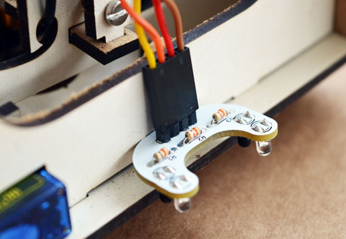
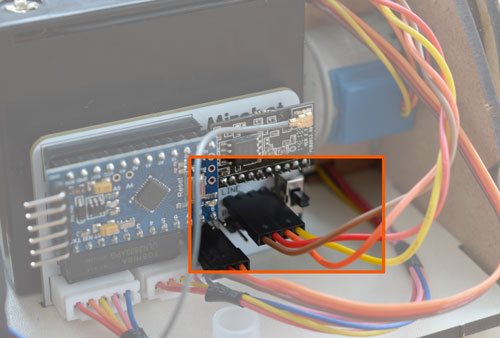
Connect the other end of this long cable on to the main PCB in the position marked “line”, making sure that the yellow wire is on the side marked GND (nearest the switch at the edge of the PCB).
Draw a line approximately 1cm thick in a black pen on white paper, then press the button in the web UI marked “Line Following” and watch as Mirobot follows the line you have just drawn. You may need to update the UI firmware in order to do this.


