This document is relevant only for the following hardware:
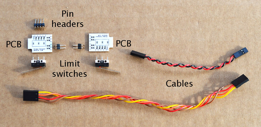
You’ll need to find the parts below to build the collision detection addon:
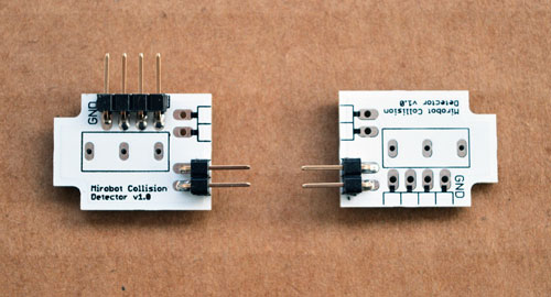
Solder the pin headers in place exactly as shown here. It’s a good idea to lay out the PCBs with the tabs facing outwards like in this picture so you can make sure that the pins are in the correct slot. Although the PCBs are the same, they need different parts soldering on depending on which side they will be.
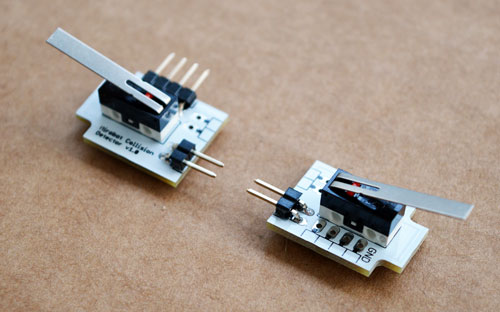
Push the two lever switches into the PCB as shown here. The holes can be a little tight but use a little force to push them all the way through and solder them in. It’s very important that the lever points in the direction of the narrow end of the PCB.
Push the tabs on the PCBs into the slots on the front sides of the chassis as shown in the picture:
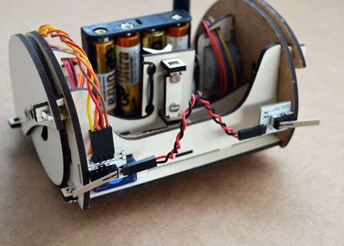
Once they are in position you should join the two PCBs together using the red and black cable. It doesn’t matter which way round this cable goes. Now you should push the longer cable on to the four pins pointing upwards. Make sure to align the yellow wire with the side of the PCB marked GND.
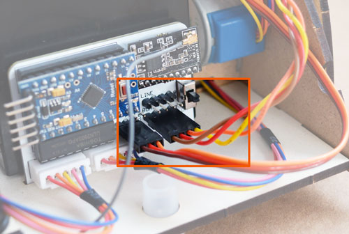
Connect the other end of this long cable on to the main PCB in the position marked “bump”, again making sure that the yellow wire is on the side marked GND (nearest the switch at the edge of the PCB).
Now you can press the button in the web UI marked “Collision Detection” and watch as Mirobot detects collisions and reorients itself. You may need to update the UI firmware in order to do this.


